
Aug 19, 2026
Zero Blind Spots: How the Matrice 400 Maps Power Line Corridors
Why do traditional utility inspections near high-voltage lines carry extreme collision risks?
Traditional high-voltage power line inspections present severe collision hazards due to ultra-thin guy wires, electromagnetic interference, and rapid weather shifts. Unshielded aircraft flying near active distribution grids risk catastrophic wire strikes, especially when navigating river valleys shrouded in UK coastal fog. Operating close to transmission towers demands active sensing systems capable of identifying non-reflective 12mm steel-core aluminium stranded wires.
Inspectors working high-voltage networks face harsh operational realities every day. Conductor cables measuring as little as 12mm in diameter are virtually invisible to optical sensors when imaged against complex background vegetation. Background clutter like dense tree canopies confuses traditional vision algorithms, while sudden gusts of wind push airframes toward energized infrastructure.
Electromagnetic fields generated by 400kV transmission lines can distort unshielded compasses and satellite navigation positioning. Visual line of sight operations in fog or low light compound these risks, creating severe pilot fatigue and high crash rates. A single wire strike results in costly hardware destruction and causes catastrophic power grid outages across regional distribution networks.
Safety regulations set by the Civil Aviation Authority mandate strict separation distances unless comprehensive risk mitigations are established. Operating under a General Visual Line of Sight Certificate or Specific Category operational authorisation requires verifiable collision avoidance hardware. Utility operators need an airframe that actively senses atmospheric hazards and thin structural elements without relying solely on optical visibility.
How do the Matrice 400 rotating LiDAR and mmWave radar create a 3D protective shield?
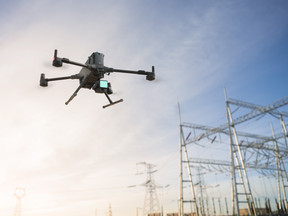
The DJI Matrice 400 integrates a 360-degree horizontal rotating LiDAR with a six-direction millimeter-wave radar array to detect thin conductors up to 36 metres away. This multi-layered sensor fusion maintains a spatial protective bubble around the airframe even in zero-visibility fog or blinding sun glare. By combining 905nm laser pulses with high-frequency radar emission, the platform identifies structural hazards that defeat traditional binocular vision sensors.
The primary defense system combines three distinct sensing technologies into an integrated safety architecture. The hardware configuration delivers omnidirectional spatial coverage tailored for linear utility corridors:
-
360-Degree Horizontal Rotating LiDAR: Emits 520,000 points per second with a 58-degree vertical field of view using a Class 1 eye-safe 905nm laser. It detects 21.6mm steel-core aluminium stranded wire at distances up to 35 metres even when the aircraft is pitched at a 30-degree tilt angle.
-
Six-Direction mmWave Radar: Operates independently of ambient lighting and atmospheric moisture. The array detects thin 12mm steel-core aluminium stranded conductors at 36 metres and larger 21.6mm lines at 50 metres across a 90-degree horizontal and vertical field of view.
-
Omnidirectional Binocular Vision System: Uses full-colour low-light fisheye sensors to maintain positioning and obstacle awareness in urban or indoor environments down to 0.5 Lux.
-
Top 3D ToF LiDAR and Downward Infrared Sensor: Provides dedicated vertical coverage from 0.5 to 25 metres at night to prevent overhead strikes against tower cross-arms and guy wires.
Radar waves pass straight through heavy fog, rain, and atmospheric dust that block optical lenses. When flying through river valleys where damp sea fog rolls in without warning, the millimeter-wave radar maintains continuous tracking of conductor spans. The onboard flight computer merges radar telemetry with point cloud data from the rotating LiDAR to render real-time spatial barriers in the cockpit view.
This dual-sensor architecture eliminates traditional blind spots above, below, and lateral to the flight direction. If a guy wire enters the flight path while the aircraft is maneuvering sideways to inspect an insulator stack, the system automatically brakes or executes an automated bypass maneuver. Operational insights show that this active shielding allows pilots to maintain steady flight tracks along high-voltage spans without manual emergency overrides.
What role does the Zenmuse H30T play during low-visibility linear corridor mapping?
The Zenmuse H30T payload combines a 1280x1024 thermal sensor, a 40MP 34x optical zoom camera, and an integrated laser rangefinder to identify thermal anomalies on grid infrastructure. Operating alongside the primary sensing shield, it allows flight crews to maintain safe standoff distances while pinpointing defective insulators and conductor hot spots. Electronic dehazing and near-infrared auxiliary illumination ensure clear visual tracking through thick mist and pitch-black night conditions.
Inspecting high-voltage assets requires rapid identification of mechanical and electrical defects before failure occurs. The Zenmuse H30T integrates five specialized hardware modules into a single stabilized gimbal system:
-
High-Resolution Thermal Imager: Features a 1280x1024 radiometric uncooled VOx microbolometer with temperature measurement capabilities spanning -20°C to 1600°C.
-
High-Magnification Zoom Camera: Employs a 40MP 1/1.8-inch CMOS sensor offering 34x optical zoom and up to 400x digital zoom for safe long-range detail capture.
-
Wide-Angle Visual Camera: Utilises a 48MP 1/1.3-inch CMOS sensor with an 82.1-degree diagonal field of view for high-density contextual imaging.
-
Long-Range Laser Rangefinder: Measures distances from 3 metres out to 3000 metres with sub-metre accuracy, generating precise GPS coordinates for pinpointed defects.
-
NIR Auxiliary Light: Emits 850nm near-infrared illumination to light up targets up to 100 metres away in pitch-dark conditions without creating visible beam distractions.
Detecting vegetation encroachment along power line rights-of-way requires calculating exact clearances between tree canopies and live conductors. Using the Laser Rangefinder PinPoint tool, the flight crew marks the conductor line and the nearest tree branch in real time. The flight computer instantly calculates horizontal and vertical separation distances, displaying the measurements on the remote controller interface.
High winds near transmission towers often cause severe gimbal shake when using telephoto lenses. The Matrice 400 applies active foreground stabilization algorithms that lock the camera frame onto specific tower fittings, such as cotter pins or dampening weights. Even when the airframe corrects against 12 m/s winds, the live video feed remains rock steady, enabling precise visual evaluation of cracked ceramic insulators.
How does a 59-minute flight time change linear corridor mapping economics?
A maximum forward flight endurance of 59 minutes reduces battery swap cycles by over 40 percent compared to legacy enterprise platforms. Extended airborne time allows utility crews to map continuous 15-kilometre transmission spans in a single flight pass. This increases daily linear throughput while reducing battery handling, ground fatigue, and unbillable downtime.
Theoretical specs must always be adjusted for real-world UK operational conditions. Carrying a Zenmuse H30T payload at sea level in windless conditions yields the maximum 59-minute forward flight figure. In actual field conditions, headwinds, low temperatures, and mandatory Return-To-Home safety margins impact available airborne time.
Real-world performance figures reflect how flight endurance translates into actual field productivity:
-
Maximum Forward Flight Time: 59 minutes tested at a constant speed of 10 m/s with Zenmuse H30T payload.
-
Realistic Usable Inspection Time: 42 to 45 minutes when accounting for a 12 m/s headwind, cold weather battery draw, and a 20 percent RTH battery reserve.
-
Maximum Horizontal Speed: 25 m/s in cruise mode, allowing rapid transit between widely spaced transmission towers.
-
Single-Pass Survey Range: Captures point cloud models and high-resolution visual data across 15 kilometres of linear corridor per flight battery pair.
Longer endurance transforms the financial metrics of linear utility surveying. Legacy platforms required battery swaps every 20 to 25 minutes, forcing operators to break flight lines, pack down ground stations, and relocate down the corridor. Fewer landing cycles preserve battery health, reduce thermal stress on power cells, and minimize team ground transport movements.
Signal reliability across long linear corridors is maintained through advanced transmission technology. The O4 Enterprise Enhanced video transmission system provides up to 40km range, supported by dual cellular dongles to prevent signal dropouts in rural areas. When flying through mountainous terrain where hills block direct signals, an Airborne Relay deployment uses a second aircraft to maintain stable, uninterrupted video transmission over obstacles.
How can operators manage regulatory compliance and CAA audits for utility BVLOS and EVLOS?
Complex linear corridor flights require structured operational management systems to satisfy Civil Aviation Authority audit requirements. Managing Extended Visual Line of Sight or Beyond Visual Line of Sight operations demands clear risk assessments, pilot qualification tracking, and maintenance records. Centralising operational workflows prevents administrative bottlenecks from delaying urgent infrastructure surveys.
Planning utility surveys near critical national infrastructure requires rigorous pre-flight planning and risk management. Operators must cross-reference flight corridors against Flight Restriction Zones, danger areas, and local land access permissions. Manual paperwork creates friction, increases human error, and slows down emergency response deployments when power grids trip.
Data highlights the operational benefits realized by major utility operators adopting centralized fleet management systems:
-
97% Reduction in Planning Time: Flight planning workflows dropped from 8 hours down to 15 minutes per mission.
- 100% Audit Readiness: Automated generation of CAA-compliant RAMS, pilot currency logs, and battery maintenance records.
Systematic record-keeping ensures every flight log, maintenance event, and risk assessment links directly to individual aircraft and payloads. Automated software workflows check airspace restrictions, fetch METAR weather forecasts, and identify emergency medical facilities near the launch site. When CAA auditors review fleet logs, complete digital audit trails demonstrate total regulatory compliance across all flight operations.
Sourcing Enterprise Hardware and Managing Fleet Compliance
Sourcing heavy-lift enterprise hardware like the Matrice 400 requires an operational partner that understands the demands of commercial utility surveying. Acquiring advanced payload systems, rotating LiDAR sensors, and millimeter-wave radar modules is only the first step toward building a successful aerial inspection program. Modern commercial drone teams must combine reliable hardware performance with organized, compliant fleet administration.
Dronedesk Shop supplies complete enterprise drone packages, Zenmuse payloads, and official accessories tailored to UK commercial operations. Paired with Dronedesk flight planning software, commercial operators gain a complete end-to-end operational ecosystem. Simplify your CAA compliance, automate complex RAMS generation, and equip your crew with the market's leading inspection platforms.
Ready to transform your utility inspection workflow with the DJI Matrice 400? Contact the experts at Dronedesk Shop to request a quotation and start your free trial of Dronedesk flight management software today.